CNC Milling Machines and Machining Centers: A Complete Guide to Tools and Tool Holder Systems
In CNC machining, cutting tools are the "teeth" that perform the work, while tool holders are the "arms" connecting the machine to the tools. Correct selection and installation are fundamental to ensuring machining efficiency, accuracy, and safety. This article provides a systematic explanation of common tools and tool holders through clear categorization and comparison.
1. Core Cutting Tools: Milling and Hole-Making
CNC tools are primarily divided into two major categories: milling tools and hole-making tools, which work together to complete the entire process from roughing to finishing.
1.1 Milling Tools
Milling cutters are multi-point rotary tools used for machining planes, contours, cavities, etc. Their types and applications are summarized in the table below:
| Tool Type | Key Characteristics & Applications | Typical Illustration |
|---|---|---|
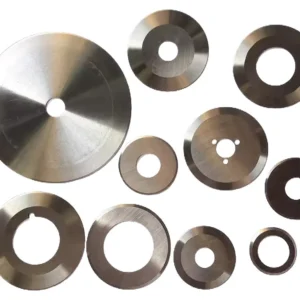
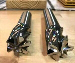
| Face Mill | A disc-shaped tool with multiple inserts, used for high-efficiency milling of large flat surfaces. | ![Face Mill] |
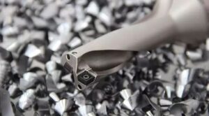
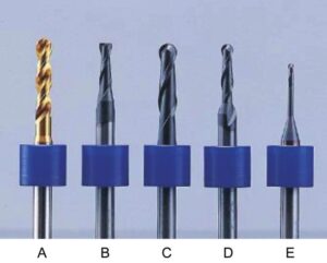
| End Mill | The most common type, available with straight or taper shanks. Can cut with both side and end edges, used for machining steps, slots, and contours. | ![End Mill] |
| Keyseat Cutter / Woodruff Key Cutter | Cutting edges extend to the center, allowing for axial plunging like a drill. Specifically designed for machining keyseats. | ![Keyseat Cutter] |
| Ball Nose End Mill | The cutting end is hemispherical, used for machining 3D contours, mold cavities, and other complex shapes. | ![Ball Nose End Mill] |
| Form Cutter | The cutting edge profile matches the specific contour of the workpiece, enabling single-pass form milling, such as gear teeth. | (Custom-made for specific shapes) |
1.2 Hole-Making Tools
Hole-making typically involves multiple operations, with different tools having distinct roles in a complete process chain.
| Tool Type | Process Stage & Purpose |
|---|---|
| Center Drill | Spotting: Creates a pilot hole at the drilling location to guide the drill and prevent walking. |
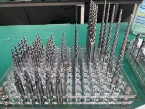
| Twist Drill | Drilling: The most basic roughing operation to create an initial hole. Available with straight shanks (small diameter) and taper shanks (larger diameter, higher rigidity). |
| Core Drill / Counterbore | Semi-finishing: Enlarges the diameter of a pre-existing hole and improves its dimensional and positional accuracy. |
| Countersink / Spotface Cutter | Hole Deburring/Finishing: Specifically machines chamfers or counterbores at the hole entrance for screw head seating. |
| Reamer | Finishing: Provides precision finishing to holes, achieving high dimensional accuracy and surface finish. |
| Boring Tool | Precision Machining: Especially suitable for finishing large-diameter holes and precise hole patterns, with adjustable dimensions. |
| Tap | Tapping: Cuts internal threads inside a hole. Machine taps are driven by the CNC, offering high efficiency. |
2. Tool Material Selection: Balancing Hardness and Toughness
Selecting the right tool material involves finding the optimal compromise between hardness, toughness, wear resistance, and cost. The properties of different materials are compared below:
| Material Type | Key Properties | Typical Applications |
|---|---|---|
| High-Speed Steel (HSS) | Good toughness, suitable for complex tool geometries, low cost; but poor heat resistance and hardness. | Low-speed machining, tools with complex shapes (e.g., form cutters, taps). |
| Carbide (Tungsten Carbide) | Hardness, wear resistance, and heat resistance are far superior to HSS. The mainstream material for modern machining. | Roughing and finishing of most steels, cast irons, and non-ferrous metals. |
| Coated Carbide | A layer of ultra-hard material (e.g., TiN, TiAlN) is coated onto a carbide substrate, further enhancing wear and heat resistance. | Demanding conditions like high-speed cutting and dry machining. The most widely used type. |
| Ceramic / Cubic Boron Nitride (CBN) | Extremely high hardness, excellent heat resistance (>1200°C); but very brittle, sensitive to impact. | High-speed finishing of difficult-to-machine materials like hardened steels and cast irons. |
| Polycrystalline Diamond (PCD) | The hardest cutting material, very low friction coefficient, but reacts with iron at high temperatures. | Highly efficient machining of non-ferrous metals, composites, and non-metallic materials. |
Core Principle: Hardness and toughness of tool materials are generally inversely related. The choice depends on the workpiece material (abrasiveness, presence of interruptions) and the machining phase (roughing prioritizes toughness, finishing prioritizes hardness).
3. Tool Holder Systems: The Precision Interface
The tool holder system directly affects the rigidity, accuracy, and dynamic balance of the machining system. The following table compares common holder types:
| Holder Type | Clamping Principle | Advantages | Disadvantages | Typical Tools |
|---|---|---|---|---|
| Collet Chuck (ER Type) | Tightening the nut causes the ER collet to contract uniformly. | Excellent versatility, high gripping accuracy, cost-effective. | Relatively lower gripping force. | The vast majority of straight-shank tools: drills, end mills, reamers. |
| Side-Lock Holder | A setscrew tightens directly against a flat ground on the tool shank. | Simple construction, high rigidity, very strong grip. | Poor gripping accuracy and concentricity, low versatility. | Roughing end mills, drills, and other tools with Weldon or similar flat shanks. |
| Hydraulic Holder | Internal hydraulic pressure uniformly expands/contracts the holder bore to grip the tool. | Excellent clamping rigidity, accuracy, and vibration damping. | Expensive, requires special equipment. | High-speed finishing, heavy roughing operations requiring maximum stability. |
| Shrink-Fit Holder | Heated to expand, tool is inserted, and cooling causes contraction for a tight grip. | Highest radial runout accuracy (≤ 3µm), best rigidity. | Requires special heating device, less convenient for tool changes. | Ultra-high-speed finishing, micro-machining. |
| Face Mill Arbor / Shell Mill Holder | Arbors for mounting shell mills/face mills using a center drawbar and drive keys. | Specifically for face mills, very secure connection. | Single-purpose, cannot hold other tools. | Various shell mill/face mill cutter bodies. |

Key Accessories:
Pull Stud: Installed at the rear of the tool holder, grasped by the machine spindle's drawbar. Must match the machine spindle type (e.g., DIN/BT, CAT).
Collet: ER collets are consumables. The correct size (e.g., ER20, ER32) must be selected based on the holder and tool shank diameter.
4. Standard Installation Procedure: Example with ER Collet Chuck and End Mill
Correct installation is the cornerstone of safety and precision. The procedure is as follows:
Step 1: Preparation and Cleaning
Tools & Parts: ER collet chuck, matching ER collet and nut, pull stud, spanner wrench, holder fixture, lint-free cloth.
Cleaning: Use a lint-free cloth with isopropyl alcohol to thoroughly clean the holder taper, collet (inside/outside), nut threads, and tool shank.
Step 2: Assembly and Tightening
1. Insert the collet into the nut.
2. Insert the tool into the collet, controlling the overhang length (keep it as short as possible while meeting the required cutting depth).
3. Hand-tighten the assembled unit (tool + collet + nut) into the holder body.
4. Secure the holder in a fixture. Use the spanner wrench to tighten the nut firmly in a clockwise direction.
5. Screw the pull stud into the rear of the holder with appropriate torque (avoid over- or under-tightening).
Step 3: Loading into the Machine Spindle
1. Clean the holder taper and spindle taper again.
2. Set the machine to Jog mode.
3. Hold the holder with your left hand, aligning its key with the spindle nose key. Press and hold the spindle "Tool Release" button with your right hand.
4. While holding the button, smoothly push the holder up into the spindle taper until fully seated.
5. Release the button. You should hear the drawbar pull the holder tight. Gently pull down on the holder to confirm it is locked.
Safety and Key Points:
Cut Prevention: Always wrap a cloth around sharp cutting edges during handling.
Prioritize Rigidity: Always follow the "minimum overhang, maximum diameter" principle.
Identify Direction: Be clear on the tightening and loosening directions for wrenches to avoid damage.
Pull Stud Torque: Tighten the pull stud with moderate force. Over-tightening damages threads; under-tightening can cause catastrophic failure.